
What are harmonics?
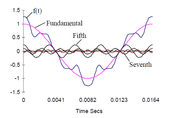
Harmonic is an unwanted interference that directly affects the quality of the power grid and should be taken into account when the total harmonic currents are higher than the allowable limit. Harmonic current is a current whose frequency is a multiple of the fundamental frequency. For example, a 250Hz line on a 50Hz grid is a 5th harmonic. The 250Hz current is an unusable energy flow with devices on the grid. Therefore, it will be converted to heat energy and cause loss.
How is the comedy line created?
Harmonic currents and voltages are generated by nonlinear loads connected to the power distribution system. All electrical energy converters used in different forms in the power system can increase harmonic noise by injecting harmonic current directly into the grid. Common nonlinear loads include motor starters, electric drive systems, computers and other electronics, electronic lights, soldering supplies, and more.
Effect of harmonics
Harmonics can cause cables to overheat, damaging insulation. The motor can also overheat or cause noise and fluctuations in the torque on the rotor leading to mechanical resonance and vibration. Capacitors overheat and in most cases can lead to dielectric destruction. Electrical displays and lights may flicker, protective devices may cut off power, computers may fail (data network) and measurement equipment may give incorrect readings.
Solution to reduce harmonic emission effects from inverters?
The transformers themselves contain nonlinear elements that are the source of harmonics. However, the harmonic current more or less depends on the structure of the drive system and the load, if using a large motor (compared to the power transformer) or increasing the motor load will increase the harmonic current. Therefore, to reduce harmonics, industrial manufacturers must use low-harmonic frequency converters or use external filtering methods. In which, in order to reduce the harmonic current, it is necessary to increase the AC, DC inductance or increase the number of rectifier valves in the rectifier and reduce the harmonic voltage caused by the harmonic current to increase the transformer capacity, reduce the transformer impedance or increase the voltage. short circuit capacity of the source.
Using 6 pulse, 12 pulse and 24 pulse rectifier
The rectifier circuit in 3-phase inverters using pulse width modulation (PWM) technology is usually a 6-valve diode bridge. Such rectifiers are simple, rugged, and cheap, but the input component contains many low-order harmonics.
A 12-valve diode rectifier bridge is made by connecting two 6-valve rectifiers in parallel, which produces a smoother current than a 6-valve bridge. Similarly, a 24-valve rectifier is simply made up of four sets of six valves together.
Using IGBT (Integrated Gate Bipolar Thyristor) bridge
An IGBT active converter can be used to rectify the input AC voltage. It will help to improve the power factor, reduce harmonics and bring many benefits such as: Safety even when power is lost; precise full-range control in rectification and regenerative modes; allowing energy to be returned to the grid; The supply current has a near sine waveform with a small harmonic component. The IGBT has less low harmonics at low frequencies, but high gain at higher frequencies; capable of raising voltage. When the supply voltage is dropped, the DC voltage can be boosted to keep the motor voltage higher than the supply voltage.
Harmonic reduction method
ABB’s harmonic reduction converters provide a simple harmonic lowering solution incorporated in the inverter. These inverters use harmonic reduction technology without the use of external filters or multi-pulse transformers. Harmonic-reducing inverters produce low-order harmonics on the input side with a total distortion current of less than 5%.
Therefore, ABB’s harmonic reduction inverters provide a simple, low-cost solution to meet stringent power quality standards.
Improve grid power quality
In inverters with 6-pulse diode bridge, the grid-side current is non-sinusoidal and contains bi-harmonic components, especially 5th and 7th order components. It is represented by a distorted current pattern, which can be up to 30-50 %. In ABB’s harmonic reduction inverter, the use of DTC (Direct Torque Control) method and filter will reduce the harmonic current by less than 5%. The result is a sinusoidal current that makes the shape of the mains voltage almost distortion-free.